This content is intended to present and illustrate generally acceptable installation methods for MEKA® cable management systems. These guidelines and information do not intend to cover all details or variations in each cable support system nor provide for every possible installation contingency. This content does neither intend to replace the responsibility of the contractor and installer to acquire knowledge of and apply the valid laws, rules, regulations, and standards on electrical and cable support system installations in each individual project and site. The installation method shall always be finally approved by the construction site supervisor and relevant authorities.
Technical requirements
Before installing and using cable management systems, please check the standards, regulations, and MEKA® installation instructions from below. In Finland, ST cards and SFS 6000 will be followed. In other regions, local rules and regulations apply.
1. Standard series SFS 6000 “Low voltage electrical installations”
2. ST card 51.06 “Fire resistant cable system for systems intended to operate during a fire”
3. ST card ST 51.13 ”Cable trays, ladders, and lightning tracks”
4. ST card ST 51.15 “Cable trunkings. Structure, design, and mounting”
5. ST card ST 51.17 “Electric cables and fire security”
6. ST card ST 51.18.01 “Soundproofing in electric lead-through installations”
7. ST card ST 51.18.02 ”Fire insulation in electric lead-through installations”
8. ST card ST 53.21 “Earthing and potential equalization of electrical installations in buildings”
General Installation Instructions
Cable management systems shall be installed in a manner that the load does not exceed the manufacturer’s specified maximum load, or that the deflection of each cable ladder/tray span does not exceed 1/100th of the span. In practice, a deflection of 1/100 means that with, for example, a three-meter-span, the deflection may not exceed 30 mm. In calculating the deflection, include roughly 50% of the existing load as additional allowance.
Sufficient gap for heat expansion shall be left between cable ladders and cable trays as well as at their ends. Steel’s coefficient for heat expansion in 0.000012m/°C. The following formula can be used to calculate the heat expansion: change is temperature x 0.000012 x length. If, for instance, the length of your tray system is 100 m and the temperature changed by 40 °C, the change in length is 40 x 0.000012 x 100 = 0.048 m, i.e. 48 mm.
The load-bearing capacity of the brackets as well as the strength of the mounting accessories and surface materials in cable ladder and cable tray installations shall be considered.
In installation sites where vertical cable ladders are prone to mechanical damage, the ladders shall be protected with a cover of 1.5 m in height.
Feedthroughs
Regarding feedthroughs in fire protection walls, cut the cable tray or cable ladder from next to the walls. At the edge of flammable areas, feedthroughs must have equivalent fire resistance to the fed-through structure.
General Installation Instructions
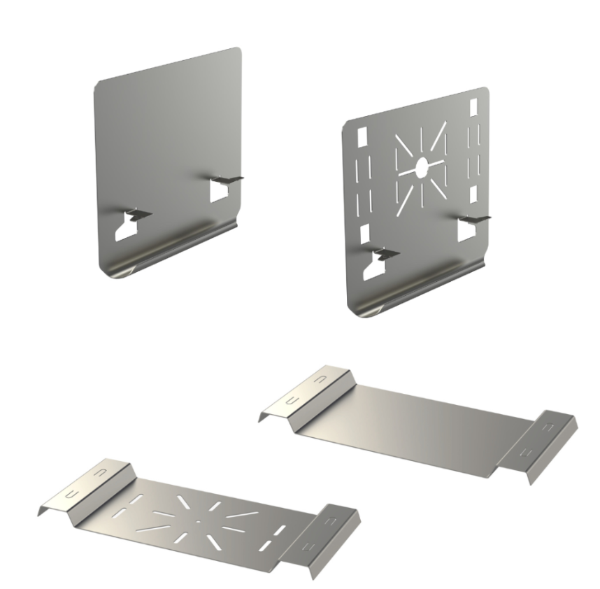
Installation accessories that are placed on cable ladders or cable trays, such as junction boxes, must be securely attached in a manner the accessories are not located in the area intended for cables. MEKA® mounting plates are recommended to be used when needed.
Use of High-Current Cable Systems
High-current cables can be installed to KS80 and KSF80 cable ladders when using cable clamps intended for that purpose.
Product Responsibility
Take note of the following regarding cable management installation:
1. Cable trays and ladders are intended to support cables only.
2. Cable trays or cable ladders may not be used as ladders or walkways. It is forbidden to attach safety harnesses or similar equipment to cable support products.
3. In installing cable management systems, consider the load-bearing specification of each component as well as the strength of the fastening and surface materials. Do not exceed the manufacturer-specified maximum load.
4. Plastic components are not intended to be used as a load-bearing element if not otherwise stated in installation instructions.
5. Products may only be installed by a qualified professional who knows safe and correct electrical contracting and construction practices, electrical equipment, and safety issues in electrical systems. The installation must always comply with standards, as well as local laws, rules and regulations.
6. Follow the manufacturer’s instructions on installation and usage.
7. Impact wrenches or other impact tools shall not be used for tightening bolts to prevent overtightening and to ensure the products’ corrosion resistance.
8. Products must be stored and handled appropriately.
9. Use only matching products of the same system with MEKA® products.
10. Make sure that mounting accessories and mounting surface meet the required strength requirements.
11. The maximum allowed (max.) load [kg] is the largest allowed load for the product in question. Verify the maximum allowed loads of each product in their product data sheets.
12. Products must not be used in the North American region.
The manufacturer assumes no liability for wrong product choices or for direct or indirect damage resulting from incorrect use.
See more information
Instructions & downloads
See more information